PDF Electric Power Distribution Systems 1 Introduction 2 Circuit Diagram
BlogPDF Electric Power Distribution Systems 1 Introduction 2 Circuit Diagram Electrical distribution system. An electrical electrical distribution system is a series of electrical circuits that delivers power in the proper proportion to homes, commercial businesses and industrial facilities. Regardless of the size and applications, the ultimate goal remains universal: the economic and safe delivery of adequate electric power to electrical equipment.

A one-line diagram for an electric power distribution system is an electrical drawing that uses single lines and graphic symbols to illustrate the current path, voltage values, circuit disconnects, fuses, circuit breakers, transformers, and panelboards.. One-line diagrams use the most basic symbols because the intent of the drawing is to illustrate as clearly as possible the flow of current power distribution 4 • At a distribution substation, a substation transformer takes the incoming transmission-level voltage (35 to 230 kV) and steps it down to several distribution primary circuits, which fan out from the substation. • Primary distribution lines are "medium-voltage" circuits, normally thought of
![[Solved]: The circuit shown in (Figure 1) is a dc model of Circuit Diagram](https://media.cheggcdn.com/media/acf/acfc6dce-b5d9-4d3d-8f5d-2464b31a5e7c/phptyJU9o)
How to Design an Electrical Power Distribution System Step by Step Circuit Diagram
The following basic considerations are fundamental to any power system design: Basic safety: The power system must be able to perform all of its basic functions, and withstand basic abnormal conditions, without damage to the system or to personnel. Basic functionality: The power system must be able to distribute power from the source to the connected loads in a reliable manner under normal
![[DIAGRAM] Simple Electric Power Distribution Diagram Circuit Diagram](https://www.researchgate.net/profile/Sen_Guo/publication/317207699/figure/fig1/AS:499379238445056@1496072696881/Schematic-diagram-of-a-generic-portion-of-Chinas-electric-power-system.png)
Designing an electrical power distribution system requires a structured approach to ensure efficiency and safety. Start by defining load requirements and selecting appropriate voltage levels. Next, design the distribution layout and choose reliable equipment. Perform calculations and document the system thoroughly.

The basics of primary distribution circuits (substation branches ... Circuit Diagram
There are several configurations of distribution systems. Most distribution circuits are radial (both primary and secondary). Radial circuits have many advantages over networked circuits including: Easier fault current protection; Lower fault currents over most of the circuit; Easier voltage control; Easier prediction and control of power flows Using software like AutoCAD, distribution design engineers draft power systems to bring electricity from distribution substations to homes. Designers have to calculate electricity usage and needs, prepare sketches, prescribe necessary equipment, estimate costs, update infrastructure, and more to make sure that power reaches customers and communities without jeopardizing the grid.

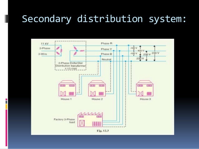
Distribution transformer: A distribution transformer, also called as service transformer, provides final transformation in the electric power distribution system.It is basically a step-down 3-phase transformer.Distribution transformer steps down the voltage to 400Y/230 volts. Here it means, voltage between any one phase and the neutral is 230 volts and phase to phase voltage is 400 volts.