Light Sensor Diagrams Circuits Circuit Diagram
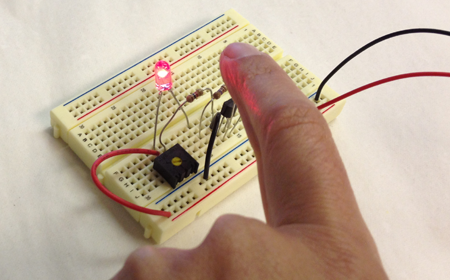
BlogLight Sensor Diagrams Circuits Circuit Diagram This is where you get to control the sensitivity of your light detector. For higher sensitivity, adjust trimmer as exact as possible to the point where the LED turns off. To decrease sensitivity, turn a little ways more after the LED has turned off. CAUTION: Ensure that the LDR is not obstructed from the light source while you perform this step. 4.

Automatic Lighting System: This circuit can be used to automatically turn on lights when it gets dark and turn them off during the day.; Light Level Indicator: It can act as an indicator for light levels in rooms or outdoors, triggering a response when light intensity falls below a certain threshold.; Solar Energy Systems: In solar-powered systems, this circuit can be used to detect light Light sensor circuits are commonly used in automatic lighting control systems to turn lights on and off based on the ambient light levels. These systems help conserve energy and provide convenience by automating the lighting process. Security Systems. Light sensor circuits can be integrated into security systems to detect motion or intrusion. In the Light Sensor Circuit (first diagram) when the brightness of light increases, the LDR's resistance reduces and so the voltage at the base of transistor increases (because if LDR resistance reduces, the voltage drop(gap) across the LDR, towards positive side decreases). Once this voltage increases above the required threshold voltage at
Arduino light sensor: A beginner's tutorial on DIY light sensing Circuit Diagram
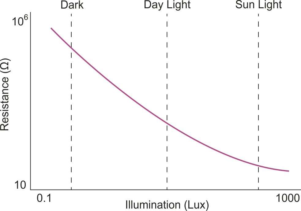
Step 11: Connect the Power Supply and the Circuit is Now Ready! How This Circuit Works. First things first: The resistance of LDR (Light Dependant Resistor) is inversely proportional to the intensity of light falling on it. It implies that if the intensity of incident light is high, the resistance of LDR will be less and vice versa.
In other words, a photodiode senses light and produces current as output. A photodiode is also called a photo sensor, photodetector, or light detector. Your First Photodiode Circuit - a Fire Sensor. You can build your first photodiode circuit using just a few components on a breadboard. This circuit will sense fire and raise an alarm. Connecting a Light Sensor to an Arduino. To connect a light sensor to an Arduino, connect the light sensor in series with a resistor between 5V and GND. Then connect the middle point between the resistor and light sensor to an analog input pin on the Arduino. This setup works with photoresistors, photodiodes, and phototransistors.
Photoresistor / Light Dependent Resistor (LDR) Circuit Explained Circuit Diagram
A tutorial on How to make a Light sensor circuit and Darkness detector circuit using LDR and transistor, along with detailed explanation on how the circuit w
